Alright, I thought I had the DSP, steppers, and limiting switches wired correctly, but apparently not.
Here is what is happening.
I plug the system in, without the Y stepper wired up. Everything appears to be working correctly, the X-stepper moves across until it bumps the frame, then moves in the other direction, hits the switch and stops.
Then I reach over and simulate the Y stepper reaching its limit switch by pressing the Y limit switch with my finger, closing the circuit.
When I do this, the X stepper starts to freakout, as if it can not make up it's mind on which direction to move. It sounds terrible.
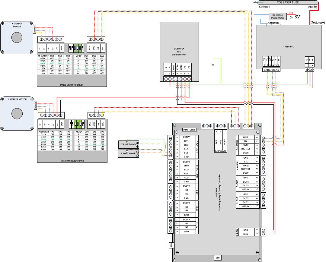
I have followed this schematic: download/DSP/LaserMachineWiringDiagram2.jpg
When I have both steppers wired, when I plug in the system, I get that same terrible sound, and it's the X stepper that is freaking out, but with the Y stepper wired, the X stepper does move, but with that grinding sounding noise. The Y stepper tries to make a move right at power up, but stops immediately.
The stepper drivers I am using are the 2m626 model.
Wiring is as follows:
X axis:
PLS+ -> DSP DC5v
PLS- -> DSP PUL (X)
DIR+ -> DSP DC5v
DIR- -> DSP DIR (x)
ENA+ -> nothing
ENA- -> nothing
GND -> -24v power
+V -> +24v power
A+ -> red wire from stepper
A- -> blue wire from stepper
B+ -> black wire from stepper
B- -> yellow wire from stepper
Y axis:
PLS+ -> DSP DC5v
PLS- -> DSP PUL (Y)
DIR+ -> DSP DC5v
DIR- -> DSP DIR (Y)
ENA+ -> nothing
ENA- -> nothing
GND -> -24v power
+V -> +24v power
A+ -> red wire from stepper
A- -> blue wire from stepper
B+ -> black wire from stepper
B- -> yellow wire from stepper
Limit switches are open until triggered:
X:
Common -> DSP GND (limit switch connectors)
Center post -> DSP ELX-
Y:
Common -> DSP GND (limit switch connectors)
Center post -> DSP ELY-
Any help would be appreciated.
John
Testing stepper motors stage of building troubles
-
jarbon
- Posts: 25
- Joined: Tue Oct 08, 2013 8:01 pm
- Contact:
-
Tech_Marco
- Posts: 4658
- Joined: Mon Jun 15, 2009 3:00 pm
- Contact:
Re: Testing stepper motors stage of building troubles
You need to make that wires on the stepping motors are paired correctly. Do NOT follow the color code on the diagram as it worked for that particular motor only. You need to find out the pair A+ A- and B+ B-.
Then, the limit switch must be Normally Opened when not engraged. When X or Y motor touched it, it should change to Closed contact and short the Ground on the DSP to either X- or Y-
BTW, it need three 'touch' to home the XY stage. Y X Y or X Y Y something like. You can stop the movement in case it doesn't react the limit switches by pressing "STOP" button the LCD
You need to double check the wiring again
Marco
-
jarbon
- Posts: 25
- Joined: Tue Oct 08, 2013 8:01 pm
- Contact:
Re: Testing stepper motors stage of building troubles
Thanks, Marco.
How do I determine which wires from the stepper are the ones that I need?
57HS22 steppers
How do I determine which wires from the stepper are the ones that I need?
57HS22 steppers
-
jarbon
- Posts: 25
- Joined: Tue Oct 08, 2013 8:01 pm
- Contact:
Re: Testing stepper motors stage of building troubles
NM.
I found this, for anyone else who needs it: http://www.leadshine.com/UploadFile/Down/57HSxxd.pdf
I found this, for anyone else who needs it: http://www.leadshine.com/UploadFile/Down/57HSxxd.pdf
-
jarbon
- Posts: 25
- Joined: Tue Oct 08, 2013 8:01 pm
- Contact:
Re: Testing stepper motors stage of building troubles
Ok, next step in this process.
I've got the jitters taken care of, however, I now have the X stepper running to the right side where the limit switch is NOT, then it jams against the frame.
So, If I am standing in front of the frame, the Y stepper is on the other side from me, and the X stepper is to my right.
I have the limit switches on the front left corner for X, and the far right corner for Y.
Is this the right set up?
Should the laser head move to the left and back to the left back corner when resetting (when turned on)? or some other way?
Do I need to move my limiting switches, or is there a software/controller setting that I'm missing?
Thanks!
John
-
jarbon
- Posts: 25
- Joined: Tue Oct 08, 2013 8:01 pm
- Contact:
Re: Testing stepper motors stage of building troubles
Marco,
I just reread your post.
Are you telling me that the X axis needs 2 limit switches, one on each side? And only 1 limit switch for the Y axis?
If so, how is the 2nd X axis limit switch wired to the DSP?
John
I just reread your post.
Are you telling me that the X axis needs 2 limit switches, one on each side? And only 1 limit switch for the Y axis?
If so, how is the 2nd X axis limit switch wired to the DSP?
John
-
Tech_Marco
- Posts: 4658
- Joined: Mon Jun 15, 2009 3:00 pm
- Contact:
Re: Testing stepper motors stage of building troubles
No, one limit switch for X and one for Y. But if you worry about the collision when motor is running opposite, you can install a limit switch on each end in parallel mode.
You can control the direction of HOME on LaserCad. Plus, you need to get a proper "um" in order for the motor to move smoothly. What machine are you running? Pictures? I always ask folks to post pictures when there is a problem to setup a machine other than K40
Marco
You can control the direction of HOME on LaserCad. Plus, you need to get a proper "um" in order for the motor to move smoothly. What machine are you running? Pictures? I always ask folks to post pictures when there is a problem to setup a machine other than K40
Marco
-
jarbon
- Posts: 25
- Joined: Tue Oct 08, 2013 8:01 pm
- Contact:
Re: Testing stepper motors stage of building troubles
Alright, here are a few pictures.
One thing that I've noticed is that for the X axis, if I press the Right button on the panel, the laser head moves Left, and the Left button moves it to the Right...
I still have the calibration to do, so I'm still looking into that.
One thing that I've noticed is that for the X axis, if I press the Right button on the panel, the laser head moves Left, and the Left button moves it to the Right...
I still have the calibration to do, so I'm still looking into that.
- Attachments
-
- The control board
-
- The laser tube will go behind and above the Y motor
-
- Rear of the frame
-
- The electronics. I still have some fitting to do.
-
Tech_Marco
- Posts: 4658
- Joined: Mon Jun 15, 2009 3:00 pm
- Contact:
Re: Testing stepper motors stage of building troubles
[quote="jarbon"]One thing that I've noticed is that for the X axis, if I press the Right button on the panel, the laser head moves Left, and the Left button moves it to the Right...
quote]
That is a simple problem and can be fixed by using LaserCad to change the direction of the movement. Please review the manual as it is clealy explained so I'm not going to explain again
Marco
quote]
That is a simple problem and can be fixed by using LaserCad to change the direction of the movement. Please review the manual as it is clealy explained so I'm not going to explain again
Marco
-
jarbon
- Posts: 25
- Joined: Tue Oct 08, 2013 8:01 pm
- Contact:
Re: Testing stepper motors stage of building troubles
Changing it in LaserCAD will change it on the control panel, then? (I'm talking about the hardware panel, not the software panel)
Who is online
Users browsing this forum: Bing [Bot] and 5 guests