Testing stepper motors stage of building troubles
Posted: Wed Oct 09, 2013 12:39 pm
Alright, I thought I had the DSP, steppers, and limiting switches wired correctly, but apparently not.
Here is what is happening.
I plug the system in, without the Y stepper wired up. Everything appears to be working correctly, the X-stepper moves across until it bumps the frame, then moves in the other direction, hits the switch and stops.
Then I reach over and simulate the Y stepper reaching its limit switch by pressing the Y limit switch with my finger, closing the circuit.
When I do this, the X stepper starts to freakout, as if it can not make up it's mind on which direction to move. It sounds terrible.
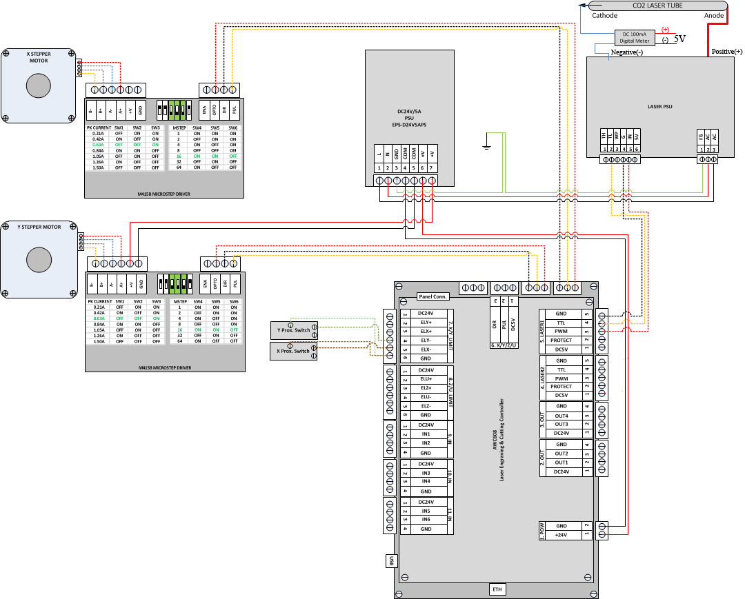
I have followed this schematic: download/DSP/LaserMachineWiringDiagram2.jpg
When I have both steppers wired, when I plug in the system, I get that same terrible sound, and it's the X stepper that is freaking out, but with the Y stepper wired, the X stepper does move, but with that grinding sounding noise. The Y stepper tries to make a move right at power up, but stops immediately.
The stepper drivers I am using are the 2m626 model.
Wiring is as follows:
X axis:
PLS+ -> DSP DC5v
PLS- -> DSP PUL (X)
DIR+ -> DSP DC5v
DIR- -> DSP DIR (x)
ENA+ -> nothing
ENA- -> nothing
GND -> -24v power
+V -> +24v power
A+ -> red wire from stepper
A- -> blue wire from stepper
B+ -> black wire from stepper
B- -> yellow wire from stepper
Y axis:
PLS+ -> DSP DC5v
PLS- -> DSP PUL (Y)
DIR+ -> DSP DC5v
DIR- -> DSP DIR (Y)
ENA+ -> nothing
ENA- -> nothing
GND -> -24v power
+V -> +24v power
A+ -> red wire from stepper
A- -> blue wire from stepper
B+ -> black wire from stepper
B- -> yellow wire from stepper
Limit switches are open until triggered:
X:
Common -> DSP GND (limit switch connectors)
Center post -> DSP ELX-
Y:
Common -> DSP GND (limit switch connectors)
Center post -> DSP ELY-
Any help would be appreciated.
John
Here is what is happening.
I plug the system in, without the Y stepper wired up. Everything appears to be working correctly, the X-stepper moves across until it bumps the frame, then moves in the other direction, hits the switch and stops.
Then I reach over and simulate the Y stepper reaching its limit switch by pressing the Y limit switch with my finger, closing the circuit.
When I do this, the X stepper starts to freakout, as if it can not make up it's mind on which direction to move. It sounds terrible.
I have followed this schematic: download/DSP/LaserMachineWiringDiagram2.jpg
When I have both steppers wired, when I plug in the system, I get that same terrible sound, and it's the X stepper that is freaking out, but with the Y stepper wired, the X stepper does move, but with that grinding sounding noise. The Y stepper tries to make a move right at power up, but stops immediately.
The stepper drivers I am using are the 2m626 model.
Wiring is as follows:
X axis:
PLS+ -> DSP DC5v
PLS- -> DSP PUL (X)
DIR+ -> DSP DC5v
DIR- -> DSP DIR (x)
ENA+ -> nothing
ENA- -> nothing
GND -> -24v power
+V -> +24v power
A+ -> red wire from stepper
A- -> blue wire from stepper
B+ -> black wire from stepper
B- -> yellow wire from stepper
Y axis:
PLS+ -> DSP DC5v
PLS- -> DSP PUL (Y)
DIR+ -> DSP DC5v
DIR- -> DSP DIR (Y)
ENA+ -> nothing
ENA- -> nothing
GND -> -24v power
+V -> +24v power
A+ -> red wire from stepper
A- -> blue wire from stepper
B+ -> black wire from stepper
B- -> yellow wire from stepper
Limit switches are open until triggered:
X:
Common -> DSP GND (limit switch connectors)
Center post -> DSP ELX-
Y:
Common -> DSP GND (limit switch connectors)
Center post -> DSP ELY-
Any help would be appreciated.
John