New LO DSP controller card with Dynamic Color LCD V7

MitchL
Posts: 71
Joined: Fri Aug 23, 2013 4:40 pm
Location: California
Contact:

Re: New LO DSP controller card with Dynamic Color LCD V7

Post by MitchL »

Greolt wrote:I use a G251 Gecko on the Z axis. This requires a common ground (unlike the G201s which drive X and Y)
Very interesting and encouraging. I used a meter, not a scope, to monitor the DIR signal on the X axis - It cannot drive all the way to 5V with the G203V installed, which is what I would expect with a weak pull up. DIR is was easy to monitor with the meter since I can turn the signal on and off by jogging. If I disconnect the G203 completely, I get a full swing from 0V to 5V on that signal. I'll use a scope next time I am tinkering.

Your G251 needs only 1ma drive on the step/dir signals. The G203V needs 2.5ma.

For this test I disconnected Y and Z and have only X connected. (so, there is only one stepper driver). I was taking the ground from the OUT connectors (which measured zero resistance to the other grounds). I

I'll double check wiring, My 708C is one of the first batch, so I wonder if the hardware is different.

You've given me some hope, thanks!

/Mitch.
Last edited by MitchL on Tue Dec 16, 2014 3:26 pm, edited 1 time in total.
Greolt
Posts: 183
Joined: Wed Dec 07, 2011 3:02 am
Contact:

Re: New LO DSP controller card with Dynamic Color LCD V7

Post by Greolt »

MitchL wrote:
Your G251 needs only 1ma drive on the step/dir signals. The G203V needs 2.5ma.
That may be why mine is OK.

Another thing is that it is only the Z axis.

If it was a bit flakey and maybe even missed steps then I probably would not notice.

Unlike it it was X or Y missing steps. That would be obvious.

I have successfully used inverters for getting around this issue on other machines.
MitchL
Posts: 71
Joined: Fri Aug 23, 2013 4:40 pm
Location: California
Contact:

Re: New LO DSP controller card with Dynamic Color LCD V7

Post by MitchL »

Greolt wrote:
MitchL wrote:
Your G251 needs only 1ma drive on the step/dir signals. The G203V needs 2.5ma.
That may be why mine is OK.

Another thing is that it is only the Z axis.

I have successfully used inverters for getting around this issue on other machines.
I was running tests with a single axis hooked up (just X). With the power off (and nothing on the connector) I'm seeing about 10K ohms from the PULS / DIR pin to 5V. It sure _looks_ like an open-drain output.

I ordered some G201X's to swap for the 203V's (I've got lots of things I can repurpose 203V's for) - if I can find some 74/74LS gates before the Geckos show up I'll build a little interposer board.

Would be really curious to know what the output drive circuit is on the 708C - if it's hung right off an FPGA or microcontroller it's likely this could be fixed in software by changing the pin config.


/Mitch.
Tech_Marco
Posts: 4654
Joined: Mon Jun 15, 2009 3:00 pm
Contact:

Re: New LO DSP controller card with Dynamic Color LCD V7

Post by Tech_Marco »

I talked to Li, the programmer who told me that the driver circuit for both X7 and the AWC608 were the same.
I sent you a new LaserCad in which it comes with a new USB driver. Give it a try


Marco
MitchL
Posts: 71
Joined: Fri Aug 23, 2013 4:40 pm
Location: California
Contact:

Re: New LO DSP controller card with Dynamic Color LCD V7

Post by MitchL »

Tech_Marco wrote:I talked to Li, the programmer who told me that the driver circuit for both X7 and the AWC608 were the same.
That's really curious then - I might just be lucky on the 608. I've removed the 708C from my laser temporarily (back to the 608), and I can set it up on the bench (with Geckodrives and stepper motors) to capture some waveforms.

I couldn't imagine why the circuit would be any different with the 708C, but the behavior certainly is, so something's different. That's why I was wondering if the output is coming directly from a FPGA, DSP, microcontroller, etc - those usually have programmable pin drives, so firmware _could_ change things. I have not opened my 708C to look at it, kind of want to keep the seal there for now.

I will also have some Gecko G201X stepper drivers on friday- they work with a common 5V pin, but I can try them either way and get some waveforms.
I sent you a new LaserCad in which it comes with a new USB driver. Give it a try


Marco
Will do - the current kit definitely does not include the NXP VCOM drivers - I'll uninstall all the drivers to make sure the new kit installs everything needed. Got lots of fun projects to work on over the break!

/Mitch.
MitchL
Posts: 71
Joined: Fri Aug 23, 2013 4:40 pm
Location: California
Contact:

Re: New LO DSP controller card with Dynamic Color LCD V7

Post by MitchL »

Tech_Marco wrote:I talked to Li, the programmer who told me that the driver circuit for both X7 and the AWC608 were the same.
I switched the drivers to Gecko 201X's which can have either a common GND or common 5V and the AWC708C can drive the steppers just fine now. The outputs are definitely open drain. I think I was lucky before.
I sent you a new LaserCad in which it comes with a new USB driver. Give it a try
The new LaserCAD seems to work - I need to make sure that it is using the driver you supplied and not the one I forced it to use.

(edit: changed section below about "blow open" and "blow closed" now that I've started making cuts)

- I just noticed the new parameters "Blow Open" and "Blow Close" - These appear to be for delays for the air assist, correct? The delays happen before and after each cut segment, but there is no delay for engraving.
- OUTPUT1 seems inverted compared to what it was before. On my 608 there was voltage on it until the job started. On the 708 the voltage appears when the job starts (which makes more sense).
- There is activity on OUTPUT2 during the pause period (but the laser should not be firing). Is this some sort of PWM signal now?

(I am using the latest version you sent me).

Bugs:

- The new LaserCAD doesn't remember the speeds and power settings for 6.88's PWJ5 files. It's no big deal (if you load old files these get default values).
- I have an old PWJ5 file that causes LaserCAD to crash. I'm happy to send it to you. It's just a bunch of vectors to cut some small gears.

Wish List:

- A "job start" delay - programmable time between when you press START and the machine starts the job.

Most important wish:

- Merry Christmas! Happy New Year!

/Mitch.
MitchL
Posts: 71
Joined: Fri Aug 23, 2013 4:40 pm
Location: California
Contact:

Re: New LO DSP controller card with Dynamic Color LCD V7

Post by MitchL »

Another bug report - I am not sure if this is the DSP or LaserCAD (7.36B). This might actually be some setting I missed, I've looked everywhere:

The origin for the job doesn't seem to be the origin of the canvas - LaserCAD makes the origin the upper-left (in my case) of the work to be cut.

For example: If I start with a blank canvas and draw a square at (100,100), then cut it, the laser will cut at (0,0) relative to the user origin.

The solution for now is to make sure there's something at (0,0) on the drawing canvas. I just add a pen run box around the workpiece and everything is fine.

Just to be clear, the hardware (limit switch) origin works fine, and the key origin also works fine (if I press RESET or Datum LaserCAD, the laser returns to the location I set in the DSP). I'm saying that LaserCAD (or something) is finding the left and top edges of the vectors and cutting relative to that.

I'll bet this is a setting in LaserCAD that I missed.

In the manufacturer and work parameters, I have everything set to Left_Up. The "position relative" is also set to Left_Up.

If I'm not explaining this well let me know, I can make a video to show you.

All in all, I'm liking the new DSP - the user interface is very quick, the new button arrangement is much better (it's awesome to have the Z axis buttons right there!), and the English text is much easier to understand. I think it's a worthwhile update from the 608. Good job, Marco and Li.

/Mitch.
(PS: How do you set the time/date at the top of the display?)
Tech_Marco
Posts: 4654
Joined: Mon Jun 15, 2009 3:00 pm
Contact:

Re: New LO DSP controller card with Dynamic Color LCD V7

Post by Tech_Marco »

Mitch:

There are 3 different way to set the Origin: Software, Key, and the machine

Software: It follow whatever image location appears on LaserCad

Key: You move the laser head to whatever point you want to be the Origin, then press the button "Origin" and the machine pick that spot as origin even though after Reset is press

Machine: It is absolute physical zero (0,0)


The front panel is my design. It intentional move the Z+/Z- from the top/bottom to the Right as I feel that it made more sens. All menu key are different thant the AWC708C and thanks to Li allow me to do the change. He is working on a custom copy of LaserCad for my X7. Once it is completed, only X7 can take advantage of new features in the future. Some guys who spent $100 less buying from China will not be able to use the new LaserCad. It is a way to protect me from my competitors. Advance version may need a dongle (security USB lock)


Marco
AndyKunz
Posts: 89
Joined: Fri May 02, 2014 12:38 pm
Location: Illinois
Contact:

Re: New LO DSP controller card with Dynamic Color LCD V7

Post by AndyKunz »

Marco,

On my machine the origin is in the top right corner. Everything I do works properly with this, except one item.

The > and < buttons move opposite. I have to push the > button to move the head to the left, and < to move to the right. The ^ and v work properly, moving the head away or towards me.

Is there a setting in the panel to correctly assign < and > buttons?

Thanks.

Andy
Tech_Marco
Posts: 4654
Joined: Mon Jun 15, 2009 3:00 pm
Contact:

Re: New LO DSP controller card with Dynamic Color LCD V7

Post by Tech_Marco »

Easy la~~~~ hammer

Open the LaserCad manufacturer parameters, change the Key direction
See image. Make sure to Save it and hit "Reset" to make it in effect.


Marco
Attachments
DSP-KeyDirection.jpg
MitchL
Posts: 71
Joined: Fri Aug 23, 2013 4:40 pm
Location: California
Contact:

Re: New LO DSP controller card with Dynamic Color LCD V7

Post by MitchL »

Tech_Marco wrote: There are 3 different way to set the Origin: Software, Key, and the machine

Software: It follow whatever image location appears on LaserCad
I've tried to figure out what this one is doing, it doesn't make much sense. My test file in LaserCAD is simple: I draw a 10mm x 10mm box whose upper left corner is at (100,100) relative to the canvas. When I run this job, the box isn't anywhere near where I expect it to be. I expect the box to be cut 100,100 from somewhere.
Key: You move the laser head to whatever point you want to be the Origin, then press the button "Origin" and the machine pick that spot as origin even though after Reset is press
This is the most useful one to me. My DSP is set to "Key".

I expect pressing "Origin" on the DSP to set the point that corresponds to (0,0) on the drawing surface in LaserCAD.

I believe the issue is related to the little blue diamond that LaserCAD shows - This appears to be the software origin, and it is calculated to be the upper-left-most part of the figure to be cut. I would like to know how I can make that blue diamond always be at (0,0). Today I do this by adding a Pen Run around my figure.

Hopefully this will illustrate: When I create a new figure and put in my box, here is what I see in LaserCAD:
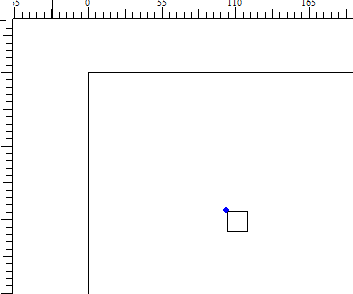
10mm square at (100,100)
WeirdOrigin.PNG (2.52 KiB) Viewed 4098 times
The blue diamond seems to be the figure's origin. I will call this the "origin dot."

If I add another figure, the "origin dot" moves along with it.
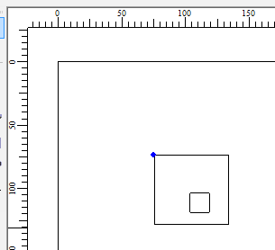
new rectangle, new origin dot
WeirdOrigin2.PNG (2.98 KiB) Viewed 4098 times
What I want is for the origin dot to be at (0,0).

When I do a project, I am sometimes lasering onto an existing workpiece that has its datum in the upper left corner. The figures to be lasered are NOT at this location, but the workpiece is. So, if I want to laser a hole at some exact coordinates on my workpiece, I would like one corner to be the datum. The workflow would be:

- Draw the holes onto LaserCAD where I want them to be relative to (0,0). (for example, by importing a DXF from a CAD model).
- Install workpiece onto the laser, jog to the corner and press ORIGIN. Now the origin corresponds to the (0,0) on LaserCAD, which corresponds to the datum in the CAD model.
- Run the job.

Current software will assume that the left/top most piece of whatever is being lasered is the origin.

Unless of course there's some way to move that blue diamond to (0,0). Today I can easily do this by just putting some figure at that location, like a pen run.

I hope this makes sense, it's not easy to explain.
The front panel is my design. It intentional move the Z+/Z- from the top/bottom to the Right as I feel that it made more sens. All menu key are different thant the AWC708C and thanks to Li allow me to do the change. He is working on a custom copy of LaserCad for my X7. Once it is completed, only X7 can take advantage of new features in the future. Some guys who spent $100 less buying from China will not be able to use the new LaserCad. It is a way to protect me from my competitors. Advance version may need a dongle (security USB lock)
Well, as I said before, I like the button layout, the speed of the LCD, and the clear English text. Very nice. I'll be happy to keep updating my X7.

/Mitch.
Tech_Marco
Posts: 4654
Joined: Mon Jun 15, 2009 3:00 pm
Contact:

Re: New LO DSP controller card with Dynamic Color LCD V7

Post by Tech_Marco »

A little confuse... I need to do more reading on your post. Unless you have a different request, the origin handling should be fine for most folks.

BTW, I have to serve a customer who bought a 1800x1200 machine from me two months ago from Oakland. May be I give you a visit sometimes on next week. That way, you can explain better to me.


Marco
MitchL
Posts: 71
Joined: Fri Aug 23, 2013 4:40 pm
Location: California
Contact:

Re: New LO DSP controller card with Dynamic Color LCD V7

Post by MitchL »

Hi Marco,

Well, it'd be great to meet you (but I'm some distance from Oakland!) - I owe you a coffee. I'd love to show you my machine, it's finally all buttoned up and nearly complete.

I guess I'm used to how I deal with the origins on my CNC machine. In the CAM tool (that generates the G-code for the machine) I set an origin for the project. All of the vectors and figures are drawn relative to that origin. Then, I put the blank workpiece on the CNC machine and set the origin on the actual machine to match the same point as the CAM tool. So, the figures I drew in CAM will be cut exactly relative to where the origin was set on the machine. The user origin on the CNC therefore represents where (0,0) is in the CAM tool.

Perhaps laser users don't think of things the same way. Here's a situation - how would a laser user handle this?

Suppose I'm engraving a sign or name plate that has already been cut. For now, let's say I have a bunch of blocks of wood 3x5 that have been pre-cut. I want to engrave a company logo in the lower right corner of each of these pieces.

Let's also assume that I don't want to use the machine origin for this, because I have a fixture that holds my 3x5 blocks in exactly the right position and orientation.

So, in LaserCAD, I draw my name plate by importing DXF's created in some other tool, or any other method. The "origin" of my 3x5 block is the upper left corner, and my engraving is drawn in the lower right corner of the 3x5 block.

The problem is that LaserCAD puts the pink diamond origin relative to the figure I drew, not the drawing page. That's fine and is a good feature for many, but it doesn't work if you're trying to laser something precisely relative to some other point. The origin button sets the point that corresponds to the blue diamond, which I totally get.

I want pressing the Origin button on the laser to set the point that corresponds to (0,0) in LaserCAD.

So: the workaround, which I'm perfectly happy with, is to draw something at 0,0 that doesn't cut. I draw a pen run box around the figure with one corner at (0,0). (in my above example it would be a 3x5 box). This causes LaserCAD to put the blue diamond at (0,0) and everything's cool.

UNLESS: there's something I don't know and there is a setting or command I've missed.

Marco, or anyone else (I'm new to laser usage) - does this make any sense at all?

/Mitch.
AndyKunz
Posts: 89
Joined: Fri May 02, 2014 12:38 pm
Location: Illinois
Contact:

Re: New LO DSP controller card with Dynamic Color LCD V7

Post by AndyKunz »

Super easy!

You make a border which it on a layer with the speed set fast and the laser set to 0%. It will draw this border, but not cut anything. That border will define the origin, and anything you put inside it will thus be relative to that origin.

Andy

PS - sounds like that's what you're already doing.
MitchL
Posts: 71
Joined: Fri Aug 23, 2013 4:40 pm
Location: California
Contact:

Re: New LO DSP controller card with Dynamic Color LCD V7

Post by MitchL »

AndyKunz wrote:
You make a border which it on a layer with the speed set fast and the laser set to 0%. It will draw this border, but not cut anything. That border will define the origin, and anything you put inside it will thus be relative to that origin.
Yep, that's kind of what I do with the "Pen Run", which is a 0% cut pass AFAIK.

So if that's the way it's supposed to be, I'm fine with it :-). I'm way too used to CNC work, can you tell? :-)

/Mitch.

Here's a video of the X7 in action:

https://www.youtube.com/watch?v=9yvCpXtua40
Post Reply

Return to “DSP X7”

Who is online

Users browsing this forum: No registered users and 3 guests