Okay! Great news: My problem is solved. The laser actually turns off when I release the test fire button.
However, now that I've wired in an ammeteraccording the wiring diagram, I'm only getting max 7.8 mA.
Rather than pop the power supply open and start screwing around, could someone tell me where the potentiometer on this laser power supply is?
I notice there's a little screw that kind of looks like a potentiometer on the back of the ammeter. Can the current be adjusted there?
Thanks again, folks. You're all real lifesavers.
Laser power supply test button LED not working
-
jgecik
- Posts: 39
- Joined: Sat Apr 13, 2013 9:16 pm
- Contact:
-
AndyKunz
- Posts: 89
- Joined: Fri May 02, 2014 12:38 pm
- Location: Illinois
- Contact:
Re: Laser power supply test button LED not working
Yup, that's it. Glad you found/fixed it!
Andy
Andy
-
parsifaldruddle
- Posts: 22
- Joined: Tue Feb 21, 2012 12:46 pm
- Contact:
Re: Laser power supply test button LED not working
So, it was a software setting the kept the laser on? Does the TEST button on the PS work now as well?
PD
(I paused my viewing of 'Scream of the Bikini' (Director Kiff Scholl) - the classic 1960s action-spy-thriller film which planted the seed for 'Charlie's Angels' - to follow these updates...)
PD
(I paused my viewing of 'Scream of the Bikini' (Director Kiff Scholl) - the classic 1960s action-spy-thriller film which planted the seed for 'Charlie's Angels' - to follow these updates...)
Last edited by parsifaldruddle on Sat Jan 31, 2015 6:33 pm, edited 1 time in total.
-
jgecik
- Posts: 39
- Joined: Sat Apr 13, 2013 9:16 pm
- Contact:
Re: Laser power supply test button LED not working
No, it was an issue with the power supply itself. I had to replace it with a newer model.
The software issue I was having was the machine prioritizing machine speeds and laser strength over speeds and strengths specified by LaserCAD. That got corrected easily, the LCD controller just forgot the setting I had put in two years ago when I bought it.
The problem I'm having now is that I'm only running 7.5mA through the laser.
Does anyone know how to turn up the amperage on this power supply?
-
parsifaldruddle
- Posts: 22
- Joined: Tue Feb 21, 2012 12:46 pm
- Contact:
Re: Laser power supply test button LED not working
Ah, okay!
re: Current Adj on PS - No, I don't - my 40w has no external adjustments, and 4 unlabeled pots mounted in the epoxy block inside. Mfr Jinan Hongyuan Electric Co., Ltd site is useless for any real info other than the niceties on the label. meh.
This Instructable shows connections and procedure for current adj. on 80x system with dissimilar PS. http://www.instructables.com/id/How-to- ... CO2-Laser/ and says to reference the PS manual (hahaha) for current adj.
The screw on the ammeter is probably for mechanically zeroing the meter.
Glad you're making progress!!
Pars
-
jgecik
- Posts: 39
- Joined: Sat Apr 13, 2013 9:16 pm
- Contact:
Re: Laser power supply test button LED not working
Thanks, Pars!
I'll have to email or ask Marco. I'm just surprised my current needs to come up instead of being turned down like everyone else, haha.
I'll have to email or ask Marco. I'm just surprised my current needs to come up instead of being turned down like everyone else, haha.
-
jgecik
- Posts: 39
- Joined: Sat Apr 13, 2013 9:16 pm
- Contact:
Re: Laser power supply test button LED not working
Okay, after reading another thread, I had the 110v/220v setting wrong on my new LPSU. A flip of the switch and we're reading at higher amps. Many thanks to Marco again.
Now I've got the opposite problem: I need the amperage turned way down. When I press the "test" button for a second or two, I read around 23mA. I did a test cut at 98% max/97% min power and my ammeter read at 27.4mA for the entire cut.
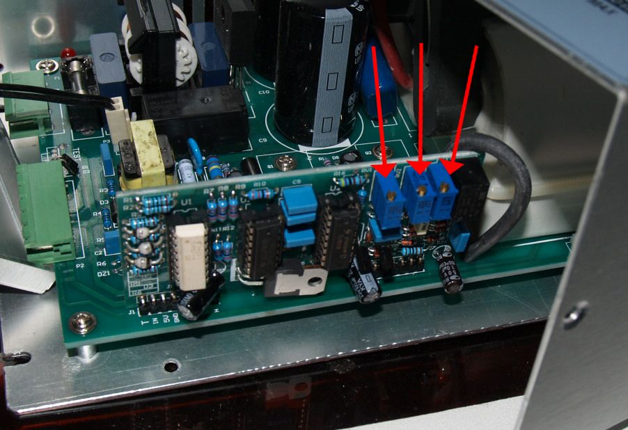
I cracked open my power supply to look for a potentiometer and found what I think are what I'm looking for. Problem is that I found three of them.
Which of these (if any) get turned to lower the current going to my tube? If none of these get adjusted to lower the current, how do I go about doing that?
Now I've got the opposite problem: I need the amperage turned way down. When I press the "test" button for a second or two, I read around 23mA. I did a test cut at 98% max/97% min power and my ammeter read at 27.4mA for the entire cut.
I cracked open my power supply to look for a potentiometer and found what I think are what I'm looking for. Problem is that I found three of them.
Which of these (if any) get turned to lower the current going to my tube? If none of these get adjusted to lower the current, how do I go about doing that?
-
Tech_Marco
- Posts: 4658
- Joined: Mon Jun 15, 2009 3:00 pm
- Contact:
Re: Laser power supply test button LED not working
You don't to do anything on those VR. To limit the peak current, you go to Option -> System tem setting -> Manufacturer parameters -> Max_power
In your case, I'll put down 65%
By the way, the purpose of those VR : V1, V2, V3 where V1 is next the black little relay, the set up is as following:
V1: 100% output current when input is max (5V signal)
V2: 50% output current when input is 50% (2.5V signal)
V3: Frequency
What I did was to use a DVRM meter to check the voltage at the phoenix terminal Gnd vs IN, then inject voltage 0V to 5V. For example, if I want the max output is limited to 18mA, then I set the output to 9mA on V2 by inputting 2.5V to the Gnd & and IN
Then, I inject 5V to the IN and turn the V1 to output until it reach 18mA. Usually we don't do anything on the frequency port as it is used for the AC power frequency response like 50Hz in China and 60Hz in USA
But, bottom line is that it is NOT necessary to play around without those setting Unless you didn't get output or out is extremely low like 4~5mA when drive the PSU in full power (100%)
Hope this help to clarify the mysterious of those three 'VR'
Marco
-
jgecik
- Posts: 39
- Joined: Sat Apr 13, 2013 9:16 pm
- Contact:
Re: Laser power supply test button LED not working
Marco,
Thanks for the suggestion, I'll try dropping the Max_Power. Now, in another thread, you mentioned that the "Max Power" setting in the export window (to send the work parameters) is then a function of that set number in Max_Power in Manufacturer Parameters. Is that correct?
For instance, I'm running at, for a hypothetical example, 30mA at 100%. If I change that to 50% in Manufacturer Parameters, I'll be running at 15mA if I tell the machine to "cut" at 100% power in the "Layer Options" in LaserCAD (and therefore at about 7.5mA if I tell Layer Options to run a cut at 50%)?
Thank you again, Marco, and everyone!
-
Tech_Marco
- Posts: 4658
- Joined: Mon Jun 15, 2009 3:00 pm
- Contact:
Re: Laser power supply test button LED not working
Yes,you are absolutely right. If manufacturer setting is 50% then the max output from the layer setting is 50% max even thought you set it to 100%
I don't like the way how it setup so I will discuss more with Li see if he can do better job on it
Marco
I don't like the way how it setup so I will discuss more with Li see if he can do better job on it
Marco
-
jgecik
- Posts: 39
- Joined: Sat Apr 13, 2013 9:16 pm
- Contact:
Re: Laser power supply test button LED not working
Now that I know the rules, it makes sense, but it could definitely be easier to use.
Thank you very much, Marco. I really appreciate the help you and the rest of the forum have given me.
UPDATE:
I made the reccommended adjustments. I'm reading 17.7mA on the ammeter and cutting smoothly.
Thanks again, gents!
Thank you very much, Marco. I really appreciate the help you and the rest of the forum have given me.
UPDATE:
I made the reccommended adjustments. I'm reading 17.7mA on the ammeter and cutting smoothly.
Thanks again, gents!
-
Tech_Marco
- Posts: 4658
- Joined: Mon Jun 15, 2009 3:00 pm
- Contact:
Re: Laser power supply test button LED not working
FYI, if you want the tube last longer, keep the current at 16mA or below.
The 720mm (32W) tube is different than a true 40W tube which indeed can take up to 18mA
Marco
The 720mm (32W) tube is different than a true 40W tube which indeed can take up to 18mA
Marco
-
jgecik
- Posts: 39
- Joined: Sat Apr 13, 2013 9:16 pm
- Contact:
Re: Laser power supply test button LED not working
Won't be a problem, I have the 45W 1M tube. I keep her around 17mA.
Thanks again!
Thanks again!
-
Tech_Marco
- Posts: 4658
- Joined: Mon Jun 15, 2009 3:00 pm
- Contact:
Re: Laser power supply test button LED not working
Having fun. Pay attention to the water temp and maintain it at 22~23'C. The tube will be happy and should serve you a long time
Marco
Who is online
Users browsing this forum: No registered users and 17 guests